Stopramp

Control Unit for Manual Skids

Stopramp

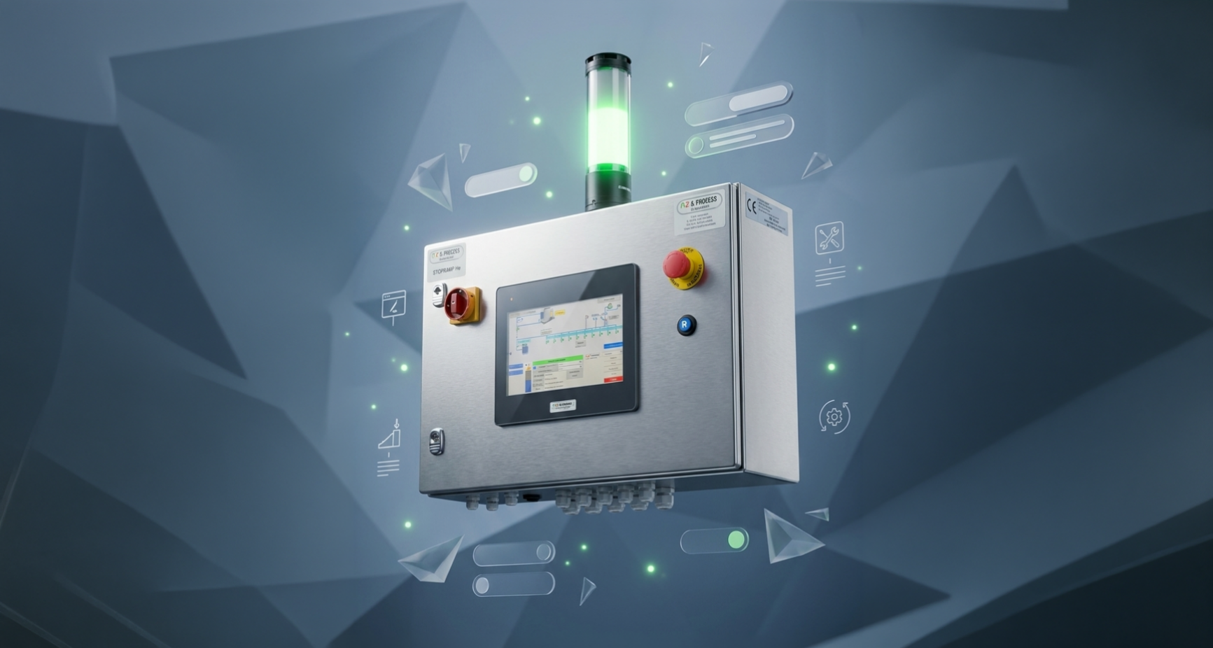
The Stopramp is a control unit developed by PLC & Process, perfectly suited for the control and safety of manual filling skids. Unlike fully automated systems, the Stopramp does not manage recipes or the automatic opening of general gas valves. Its integration allows a manual skid to be upgraded to a Semi Automated Filling Tool (SAFT). It is compatible with the requirements of the industrial, food, and medical sectors.

Request a Quote Datasheet ← Back

Operation & Steps

  • Manual control: The operator manually opens the skid valves before interacting with the interface.
  • Available steps: 3 distinct steps activatable from the touch screen: Filling, Purge, Vacuum.
  • Valves: Ability to integrate a low/high flow valve on the main line, and regulation valves on gas inlets and the purge.

Safety Recommendation

  • Recommended automation: Although designed for manual operations, it is highly recommended to automate at least the vacuum step (and associated valves).
  • Error prevention: This partial automation prevents operator handling errors and significantly increases process safety.

Interface & Security

  • Front panel: Main disconnect, emergency stop, and reset push button (for SIL board).
  • User interface: 10" touch screen with integrated RFID card reader.
  • Safety logic: SIL-3/4 board integrated.

Electrical & Hardware Characteristics

Power supply: 230/400 VAC.
Vacuum pump interface: Standard sizing for 3kW pump control.
Dimensions (H x W x D): 400 mm x 600 mm x 200 mm.
Mounting system: 4x wall mounting brackets.
Display Units: Configurable in Bar/PSI, °C/°F, and Liters/Gallons.
Remote assistance: Secure access for maintenance (if 4G VPN modem option is present on site).
Operating temperature: Standard 0°C to +50°C (other upon request).

I/O Boards Details

Input boards: for element feedback.
Analog input boards: for sensors.
RTD input boards: for temperature probes.
Output boards: for valve control (24VDC Max 8W).
Analog output boards: for regulation valve control.

Interactive P&ID Diagram

Hover over the hotspots to explore the Piping and Instrumentation Diagram (P&ID) of the Stopramp system.

Gas inlet
Connection to the gas source.
Filling outlet
Connectable to manifolds, bundles, or multiple containers on the same line.
Vacuum circuit
Line connected to the pump to ensure a perfect vacuum before filling.
Vent circuit
Secure evacuation line to depressurize and purge piping between two cycles.
×

System Selector